System Overview
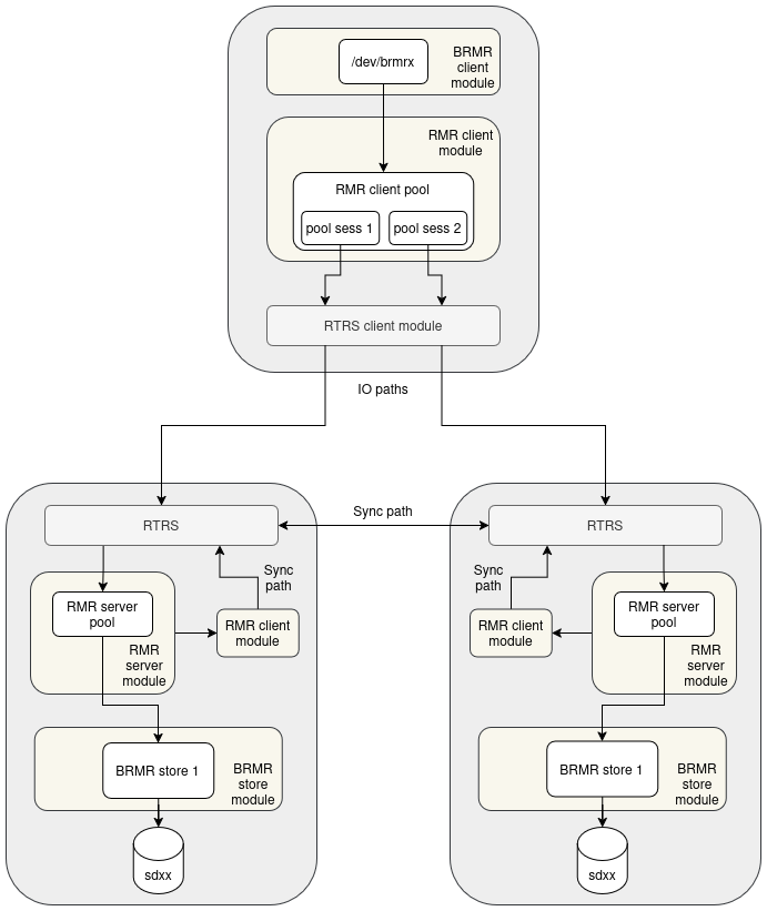
The diagram above shows a minimal RMR deployment for one rmr pool: one compute client and two storage nodes. Each arrow represents a module boundary and a direction of data flow.
Compute client
The compute client exposes a /dev/brmrX block device to applications via the BRMR client module. Below it, the RMR client module maintains an RMR pool. The pool holds one session per storage node (pool sess 1, pool sess 2). Each session maps to an RTRS connection managed by the RTRS client module.
On the IO path:
Write requests are replicated to all sessions in NORMAL state. A write is acknowledged to the caller as soon as it succeeds on at least one session; failures are tracked in the dirty map.
Read requests are distributed across sessions in a round-robin fashion.
The RMR client is also responsible for control-plane operations across all pool members: map updates, session state transitions, and recovery coordination.
Storage nodes
Each storage node runs a symmetric stack. Incoming IO from the compute client arrives at the RTRS server module and is passed to the RMR server module, which owns the pool on the server side. The RMR server forwards IO to the backend via the BRMR store module, which owns the physical disk (sdxx).
The RMR server handles commands from the client (join, enable, map updates) and tracks dirty chunks on behalf of the pool.
Sync path
Each storage node also runs an RMR client module and an RTRS client module that connect to the other storage node. This is the sync path: when a storage node needs to recover dirty chunks, it reads the missing data directly from its peer over this connection, without involving the compute client. The sync path reuses the same RMR client and RTRS infrastructure as the IO path.